Specific technologies PDH deficiencies have been addressed and overcome technology developers synchronous optical networks (Synchronous Optical NET, SONET), the first version of the standard which appeared in 1984. It was then standardized Committee of T-1 ANSI Institute. As a result of long work ITU-T and ETSI managed to prepare an international standard SDH (Synchronous Digital Hierarchy - Synchronous Digital Hierarchy).
The main goals of SDH developers were:
- Continuity of existing digital channels T1-T3, E1-E3
- Ensuring the hierarchy of speeds far exceeding the speed of plesiochronous digital hierarchy (PDH)
Hierarchy speeds
In all of the standard SDH rates levels (and accordingly, frame formats for these levels) are collectively termed STM-N (Synchronous Transport Module level N - synchronous transport module of level N). In SONET technology, there are two designations for the velocity levels: the name of the STS-N (Synchronous Transport Signal level N - synchronous transport signal level N) is used in the case of data transmission electrical signal, and the name of the OC-N (Optical Carrier level N - fiber level link N) is used in the case of data transmission over fiber optic cable.
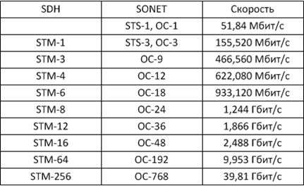
Hierarchy SDH speeds Hierarchy SDH speeds originally developed with the expectation that the smallest SDH frame, i.e. STM-1 was able to transmit the largest frame PDH in the European version. In this multiplexing scheme takes into account both the packaging streams T1 to T3, so E1 to E3 streams.
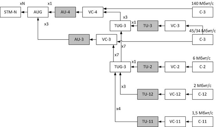
Scheme SDH multiplexing data
VC - Virtual Container
TU - Tributary Unit
AU - Administrative Unit
Cross-connect tables
Virtual containers are switching unit SDH multiplexers. Each multiplexer exists connection table (also called cross-connect table) which indicates for example that the container VC-12, the port P1 connected to the port P5 container VC12, VC3 and container port P8 - container VC3 port P9. Table of compounds forms a network administrator using a management system or a control terminal on each multiplexer to provide a through path between end points of the network, which is connected to the user equipment.
Pointer
In addition to the blocks of data in the PDH virtual container is put some more official information, in particular the title path (Path OverHead, RON). AU and TU also contain additional header with a pointer that points to the beginning of the payload in the VC. This index allows to combine in a single network SDH and synchronous nature of the asynchronous nature of PDH.
It is thanks to the system of indicators multiplexer is the position of the user data in a synchronous byte stream STM-N frames and "on the fly" removes them out, then the multiplexing mechanism used in of PDH, does not allow. Therefore in communication lines that are based on SDH networks greatly reduces the amount of active equipment, because the costs of recovery of the user channel from the total flux is significantly lower than in the networks of PDH.
Types of equipment
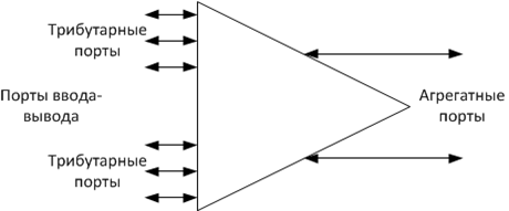
Multiplexor SDH Multiplexers SDH networks are divided into:
- terminal multiplexers, which produce okonechivayut line and all input and output streams in the communication line;
- input-output multiplexer, which is responsible for input-output streams for only a portion of the end user.
At multiplexers are input-output ports, also called tributary ports, as well as aggregates, ie linear ports.
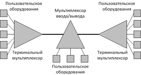
Multiplexors SDH:
Terminal Multiplexer, ТМ
Add-Drop Multiplexer, ADM
Stack of SDH protocols
SDH protocol stack is composed of protocol 4 levels. These levels did not correlate with the levels of the OSI model, for which the entire network SDH equipment is represented as a physical layer.
- Photon level - has to do with the encoding of information bits by light modulation.
- section level - maintains the physical integrity of the network;
- Line level - is responsible for the transfer of data through the network between two multiplexers;
- tract level - is responsible for the delivery of data between two end users of the network.
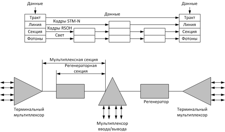
Stack of SDH protocols
The frame structure STM-1
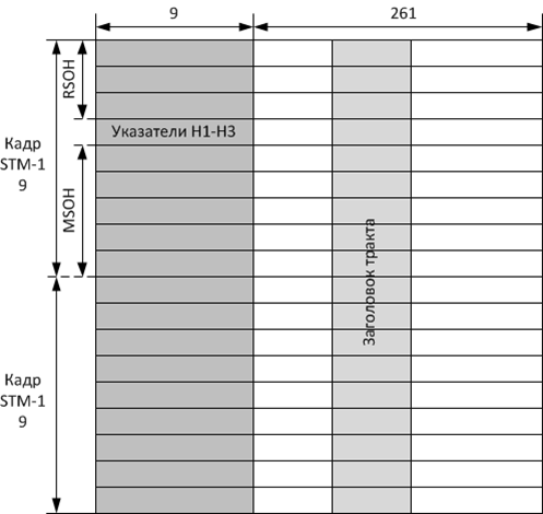
The frame structure STM-1 Frame typically in the form of a matrix consisting of 270 columns and 9 rows.
The first 9 bytes of each row are reserved for overhead data header of the next 261 bytes 260 are reserved for the payload (data structures such as AUG, AU, TUG, TU and VC), and one byte of each string - a tract header, allowing control Connect "from end to end."
RSOH - header regenerator section.
MSOH - header multiplex section.
| Header regenerator section | Header multiplex section |
|---|---|
| Sinchro bytes | Bytes for error checking multiplex section |
| Bytes for error control Regenerator Section | Six bytes of data transmission channel operating at a speed of 576 Kbit / s |
| One byte service audio channel (64 kbit / s) | Two bytes automatic traffic protection protocol (bytes K1 and K2), which provides network survivability |
| Three bytes of data link (Data Communication Channel, DCC), operating at a speed of 192 kbit / s. | Byte messaging system synchronization status |
| The bytes reserved for national operators | The remaining overhead bytes MSOH or reserved for national carriers, or not used |
| Fields pointers H1, H2, NC set start position of the virtual container VC-4 or three virtual containers VC-3 with respect to pointer fields |
