The technology packed wavelength division multiplexing (Dense Wave Division Multiplexing, DWDM) is designed to create a new generation of optical backbones running at multi-terabit speeds and. Information in fiber-optic communication lines passed at the same time a large number of light waves. DWDM networks operate on the principle of channel switching, each light wave is a single spectral channel and is essential information.
Opportunities of DWDM
The number of channels in a single fiber - 64 light beams in the 1550 nm window transparency. Each light wave transmits information at 40 Gb / s. hardware development is also underway with data rates at speeds of up to 100 Gbit / s and Cisco, are already in progress to develop such technology.
In DWDM technology has predecessor - wavelength division multiplexing technology (Wave Division Multiplexing, WDM), which utilizes four spectral channel transmission windows 1310 nm and 1550 nm, with a carrier spacing of 800-400 GHz. Multiplexing DWDM called "densified" due to the fact that it uses a considerably smaller distance between the wavelengths than the WDM.
Frequency plans
At present, two of the frequency plan (ie a set of frequencies that are separated from each other by a constant value) are defined recommendation G.692 Sector ITU-T:
- The frequency plan pitch (spacing between adjacent frequency channels) of 100 GHz (0.8 nm = YES), whereby the data transmission wave 41 is applied in the range of 1528.77 (196.1 THz) to 1560.61 nm ( 192.1 THz);
- Frequency plan in increments of 50 GHz (YES = 0.4 nm), allowing you to transfer in the same range of 81 wavelengths.
- Some companies also produced equipment, the highly-called wavelength division multiplexing equipment (High-Dense WDM, HDWDM), capable of operating with a frequency up to 25 GHz increments.
The main problem in the construction of super-dense DWDM systems is that with decreasing frequency step there is an overlapping of the spectra of adjacent channels and there is blurring of the light beam. That leads to an increase in the number of errors and the inability to transmit information on the system
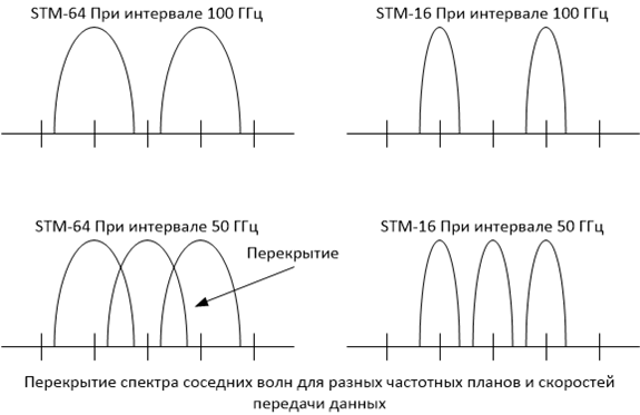
Frequency plans of DWDM In the following channel plans are currently being used for various types of DWDM systems, CWDM, HDWDM, WDM.
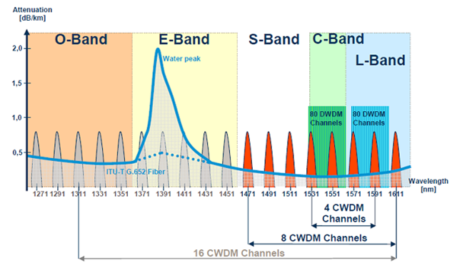
Frequency plans DWDM ## Optical fiber amplifiers
The practical success of DWDM technology in many ways defined the appearance of a fiber-optic amplifiers. Optical devices directly amplify light signals in the 1550 nm band, eliminating the need of intermediate conversion to electrical form, as do the regenerators used in the SDH network. The disadvantage of systems of electric signal regeneration is that they have to take a certain type of coding, which makes them quite expensive. Optical amplifiers, "transparent" transmission information, allow to increase the line speed without the need to upgrade the amplifier units. Length of the section between the optical amplifiers can reach 150 km or more, which provides economical DWDM backbones generated in which multiplex section length is today 600-3000 km with use of 1 to 7, the intermediate optical amplifiers.
Recommendation ITU-T G.692 defined three types of amplifying sections, ie sections between two adjacent multiplexers, DWDM:
- L (Long) - plot consists of a maximum of 8 spans of fiber-optic communication lines and 7 of optical amplifiers, the maximum distance between the amps - up to 80 km with a maximum total length of the section of 640 km;
- V (Very long) - plot consists of a maximum of 5 spans of fiber-optic communication lines and 4 optical amplifiers, the maximum distance between the amps - up to 120 km with a maximum total length of 600 km section;
- U (Ultra long) - plot without repeaters up to 160 km
Restrictions on the amount of coasting and long associated with the degradation of the optical signal in the optical amplification. Although optical amplifier restores the signal strength, it does not fully compensate for the effect of chromatic dispersion (i.e. propagation of different wavelengths at different rates, due to which the signal at the receiving end is "smeared" fibers) and other nonlinear effects. Therefore, to build a more extensive highways need to be installed between the reinforcing portions DWDM multiplexers performing signal regeneration by converting it into electrical form and back. To reduce non-linear effects in the DWDM signal limitation also applies power systems.
Типовые топологии
Ultralong two-point connection on the basis of terminal multiplexers, DWDM
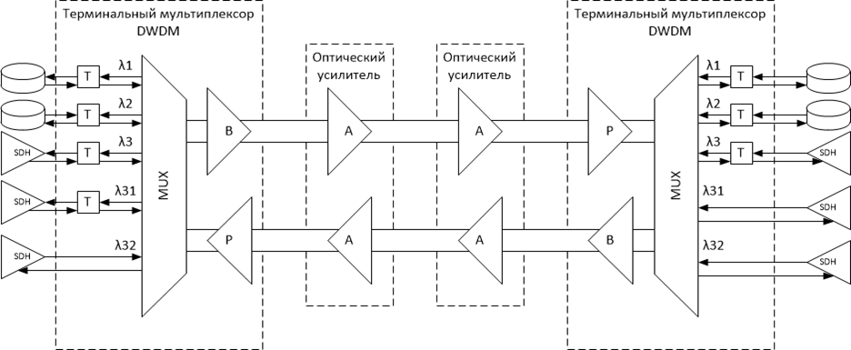
Ultralong two-point connection on the basis of terminal multiplexers, DWDM DWDM circuit with input-output in the intermediate nodes
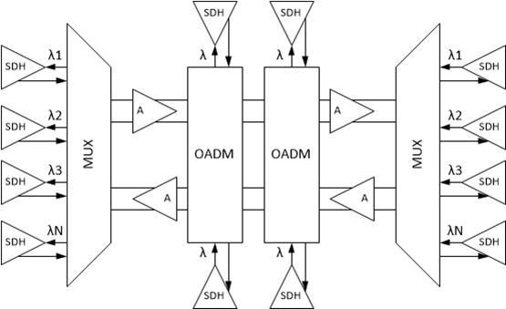
DWDM circuit with input-output in the intermediate nodes Ring topology
The ring topology provides survivability DWDM network through redundant paths. traffic protection methods used in of DWDM, similar to the methods in SDH. To some the connection was secured, two paths are established between its endpoints: main and reserve. Multiplexer endpoint compares the two signals and selects the best signal quality.
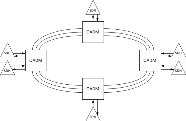
Ring DWDM multiplexers The mesh topology
With the development of DWDM networks are increasingly mesh topology is used, which provides the best performance in terms of flexibility, performance, and resiliency than other topologies. However, to implement a mesh topology, you must have optical cross connects (Optical Cross-Connector, PL), which not only add waves to the overall transit signal and outputting them out, as do the multiplexer input-output, but also support arbitrary switching between optical signals transmitted waves of different lengths.
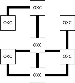
Mesh DWDM ## Optical multiplexers IO
Passive muliplexers used in DWDM networks (without power supply and active conversion) and active multiplexers, demultipleskory.
| Passive multiplexers | Active multiplexers |
|---|---|
| The number of light waves output low | The number of light waves is limited to the applicable frequency plan and a set of light waves |
| It allows you to display and input signal is a light wave without changing the overall spectrum of the light beam | It does not introduce additional attenuation because it produces a complete demultiplexing of all channels and converting into electrical form |
| Introduces additional attenuation | It has a high cost |
| It has a budget cost |
Optical cross-connects
In networks with mesh topology is necessary to provide the flexibility to change the route of the wave of connections between network subscribers. Such capabilities provide optical cross-connects, to guide the any of the waves at any output port from each input port signal (of course, provided that no other signal of this port does not use the wave must perform another broadcast wavelength).
There are optical cross-connects two types:
- Optoelectronic cross connectors with intermediate conversion to electrical form;
- all-optical cross-connects, or photonic switches.
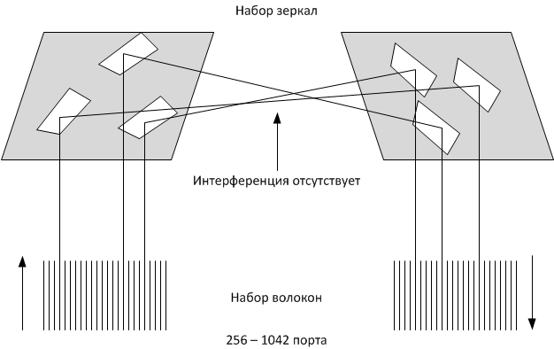
MicroElectro Mechanical System, MEMS ## Factors to be considered in the construction of DWDM systems
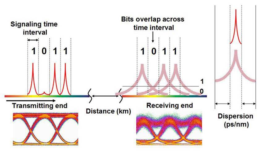
Chromatic dispersion Chromatic dispersion - as a result of its influence, as it propagates through the fiber, the pulses constituting the optical signal become wider. When transmitting signals over long distances pulses can be superimposed on the adjacent, making it difficult for accurate recovery. With increasing speed of the transmission optical fiber length and chromatic dispersion effect increases. To reduce the effect of chromatic dispersion on the transmitted signals, dispersion compensators are applied.
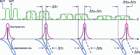
Polarization Mode Dispersion PMD occurs in an optical fiber due to the difference in the propagation velocities of the two mutually perpendicular polarization mode components, which leads to distortion of the transmitted pulses. The reason for this phenomenon is the heterogeneity of the geometric shape of the optical fiber. Effect of polarization mode dispersion on the transmitted optical signals with increasing rate with increasing number of channels and sealing system with increasing fiber length.
Stimulated backscatter Mandelstam - Brillouin, the essence of this phenomenon is to create an optical signal of periodic domains with varying refractive index - a kind of a virtual diffraction grating, passing through which signals propagate like the acoustic wave. Reflected this virtual grid signals are added and amplified to form a reverse optical signal with the Doppler frequency down. This phenomenon leads to an increase in the noise level and prevents the spread of the optical signal, since a large part of its power is dissipated in the reverse direction. Often mistakenly called this phenomenon reflected acoustic wave.
Phase modulation at high power levels of the laser signal modulation of its own phase of the signal can occur. This modulation extends the range and broadens or compresses the signal in time, depending on the sign of the chromatic dispersion. In dense WDM systems, self-modulation signal with an expanded spectrum signals may be superimposed on the adjacent channels. Phase modulation signal is increased with increasing power, increasing the transmission rate and with a negative chromatic dispersion. Influence of phase modulation is reduced at zero or a small positive chromatic dispersion
Cross-phase modulation, the phenomenon resulting signal modulates the phase of one channel signals from neighboring channels. Factors affecting the cross-phase modulation, coincide with the factors influencing the phase modulation. In addition, cross-phase modulation effect depends on the number of channels in the system.
Four-wave mixing, is shown at the threshold power level laser, in which case the non-linear characteristics of the fiber leads to the interaction of three waves and the fourth wave of the new appearance, which may coincide with the frequency of another channel. Such overlay frequency increases the noise level and signal reception difficult
Insertion EDFA amplifier noise, the reason for this phenomenon - the power of the amplified spontaneous emission that occurs due to the design features edfa amplifiers. In the process of passing through the amplifier to the useful component of the optical signal is added to the noise, thereby reducing the ratio of "signal / noise" as a result of the signal can be received in error. This phenomenon limits the amount of in-line amplifiers.
