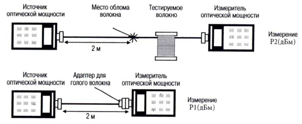
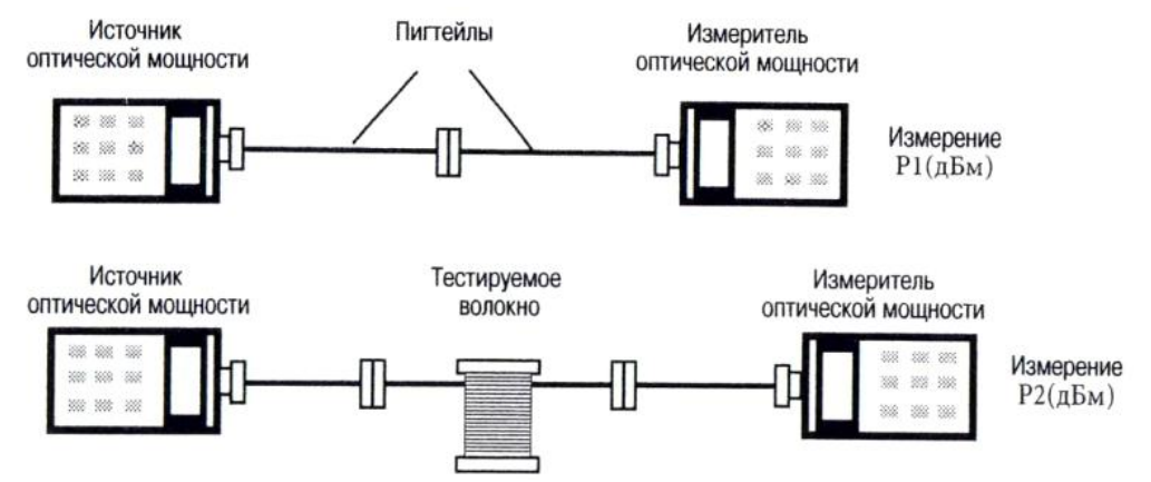
There are two methods of measuring the loss in the optical fibers which, in accordance with G. 651 and G. 652, is considered the reference - fiber breakup method and the method of insertion loss. The loss measurements are made by means of optical testers. In the method of fiber breakup P1 measured power (in dBm), passed through the fiber. The fiber breaks off at a distance of about two meters away from the injection point and measured radiation power P2 (dBm), passed through a short section of the remaining fiber. The value of loss in the fiber is determined as the difference between A (dB) = P1 (dBm) - P2 (dBm)

Measurement of losses by the breakup of fiber
Method breakup fibers provides the highest accuracy, since it share power introduced in the fiber remains unchanged. Its disadvantage is that the fiber integrity is violated and can not be used during installation of the transmission line. Therefore, the more common method is the insertion loss. In this method, the first reference power measured value P1 (dBm). Then, between the optical power meter and a source of optical radiation is inserted into the fiber under test, or the transmission line and the measured value is transmitted power P2 (dBm). Loss value determined as a difference A (dB) = P1 (dBm) - P2 (dBm).

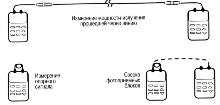
Measurement method of insertion loss insertion loss method used when measuring the total losses in the transmission line. Due to the fact that the line ends are usually spaced a long distance, it is necessary to perform an additional calibration of the laser and photodetector module in such measurements. The photodetector unit optical tester, paragraph A, is used to measure the reference value of the power of the laser emission unit and a light receiving unit of the optical tester, paragraph B - for measuring radiation power transmitted via the communication link.
First, an operator located in A, connecting the input and output optical tester optical cord, measures the magnitude of the reference signal. Then disconnect the power connector from the photodetector unit outlet and connects it to a port on the line in input. The operator, who is in paragraph B, connects via optical cable to your optical tester line output and measures the signal. Then, using an optical phone (or any other way) it reports the measurement result to the operator who is in point A. The value of loss (based on the difference of the photodetector units obtained in the process of verification) is calculated by the formula: A (dB) = reference signal in dBm - signal in dBm.

Measurement losses in fiber optic with optical testers In this arrangement the measurement error occurs for the following reasons:
- instability of the radiation source
- nonlinearity of the meter scale
- different sensitivity photodetector units at opposite ends of the line
- deviations of the losses in the connectors on their nominal value
Short-term instability of the laser unit (for example, passport data AQ 2150) is equal to 0.02 dB, actually, she does not exceed the price of division of its scale (0.01 dB). Stability of the LED unit is higher than that of the laser, but when used in fiber loss value is exaggerated by about 5% due to the relatively broad bandwidth LED emission (50 ... 100 nm).
Tester optical nonlinearity in the range from 0 to 30 dB are not greater than the division value. The error occurs because of the different sensitivity photodetectors blocks is eliminated by checking their testimony before the loss measurements in line and after their completion. The greatest uncertainty arises from the fact that it is not known precisely the magnitude of losses in the connectors.
As you know, when connecting connectors "any to any" value of the losses in the place of connection of connectors may differ from the nominal value on the order of the average value of these losses (~ 0.2 dB). This uncertainty in the magnitude of the loss connectors and give the main contribution to the resulting error that occurs when measuring the total loss in the line.
Although the loss in single-mode fiber does not depend on the direction of light propagation, loss measurements taken hold line in both directions. Thus, it is possible to eliminate some systematic errors. For example, if by mistake to a single mode fiber () has been welded from a multimode fiber pigtail. Then the losses in the lines will depend on the direction of light propagation (i.e. differ more than a measurement error), as the transmission rate from a single-mode fiber is greater than the part of the multimode fiber. Or, for example, by averaging the results of the loss measurements in opposite directions, it is possible to eliminate systematic error that arises due to the different sensitivity photodetectors multimeters blocks located at opposite ends of the line.
