The most important parameters are the optical fiber loss and attenuation of the transmitted energy. These parameters define the range of the FOC and on its effectiveness. Attenuation in optical fibers due to manifestation of the following losses:

α
c
– own loss of fiber waveguides
α
k
– additional cable losses
α
ik
– absorption loss in the infrared region
α
pr
– the loss caused by the presence of impurities in the optical fibers
Proper loss fibers consist, in turn, an absorption loss of α p and scattering loss α r :

Attenuation due to the absorption due to the losses on the dielectric polarization depends strongly on the properties of the fiber material and is calculated by the following formula:

tgδ – dielectric loss tangent
The attenuation in the infrared region, situated in the wavelength range of more than 1.6 microns, calculated by the formula:

C and k – constant coefficients. For quartz glass C = 0,9; k = (0,7—0,9) мкм.

In the scattering of light at inhomogeneities rays diverge in directions of which has a smaller angle of incidence than the angle of total internal reflection. Some rays while leaving the core and go to the shell, and the other, remaining in it, come back to the radiation source. This scattering is present in any optical fiber; it is called Rayleigh scattering. Attenuation on the scattering can be estimated using the following formula:

С – Rayleigh scattering coefficient.

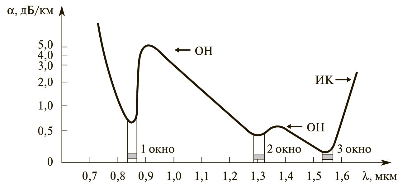
One of the concepts in the concept of transparency is a fiber optic window. This region in the light emission spectrum of frequencies in which the attenuation in the fiber is minimal. It is at these wave lengths of light emission in the production of oriented fiber optic transceivers. The first transparent window occurs at a wavelength of 0.85 microns, at which the attenuation value of 1.8 dB / km, the second corresponds to a wavelength of 1.31 microns, at which the attenuation is 0.36 microns, and the third wavelength is observed at 1, 55 microns, at which the attenuation was 0.22 dB / km.

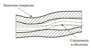
During the manufacture of fiber optic cables have additional, so-called cable losses, which include loss of macro and microbending. In the manufacture of optical fiber cable in the cable in a freely located because the fiber is subject to destruction under tension more than 1%. Hence the length of the optical fiber cable is usually longer than the length of the cable. In the macro fiber and microbends arise when the location in the cavity of the optical fiber cable, which also affects the attenuation of the light signal when the light beam incident on the optical fiber medium boundary at an angle that is greater than the angle of total reflection. Thus, the light beam goes beyond the optical fiber core.

Loss may also arise by random microbends of the optical fiber, which occur during the blending of the protective coating and the manufacture of optical fibers as a result of thermal expansions and contractions directly and fiber coatings. Span deviations of less than 1 micron, and the step of - at least 1 mm. By Macrobends also includes optical fiber bend as a result of installation of cable lines or laying cable stocks in telecommunication cabinets when neglected recommended minimum optical cable bending radius.
